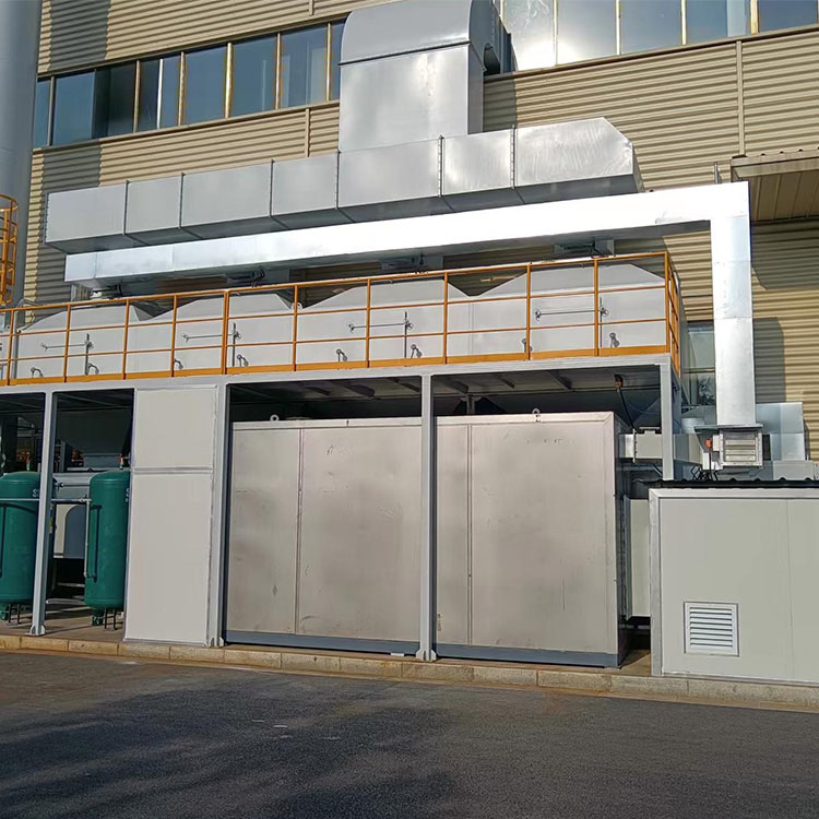
Lvquan Catalytic Combustion Equipment L, produced by a renowned manufacturer and supplier in China, offers competitive prices and outstanding quality, making it a highly sought-after choice for efficient and environmentally responsible combustion solutions.
The Lvquan Catalytic Combustion Equipment L, provided by a reputable manufacturer and supplier based in China, presents a holistic solution for efficient and eco-friendly combustion processes. With competitive pricing, this equipment stands out as a cost-effective option across various industrial sectors. Its outstanding quality reflects the manufacturer's unwavering dedication to delivering top-tier performance and longevity. Leveraging cutting-edge catalytic combustion technology, the Lvquan equipment ensures the conversion of energy is both clean and highly efficient. Whether you're seeking to enhance your current combustion setup or installing a new system altogether, opting for this equipment guarantees exceptional performance, value for money, and a commitment to environmental preservation.
Catalytic Combustion Equipment Luses low-temperature oxidation technology,which is to heat organic gases to the decomposition temperature under the action of precious metal catalysts to purify the gas.
1.Industry Application:Common pollutants discharged from industries such as petrochemicals, light industry,plastics, printing, and coatings, etc.
2.Waste Gas Type Application: Catalytic Combustion Equipment L (aromatic hydrocarbons, alkanes, alkenes), benzene, ketones, phenols, alcohols, ethers, alkanes, and other compounds.
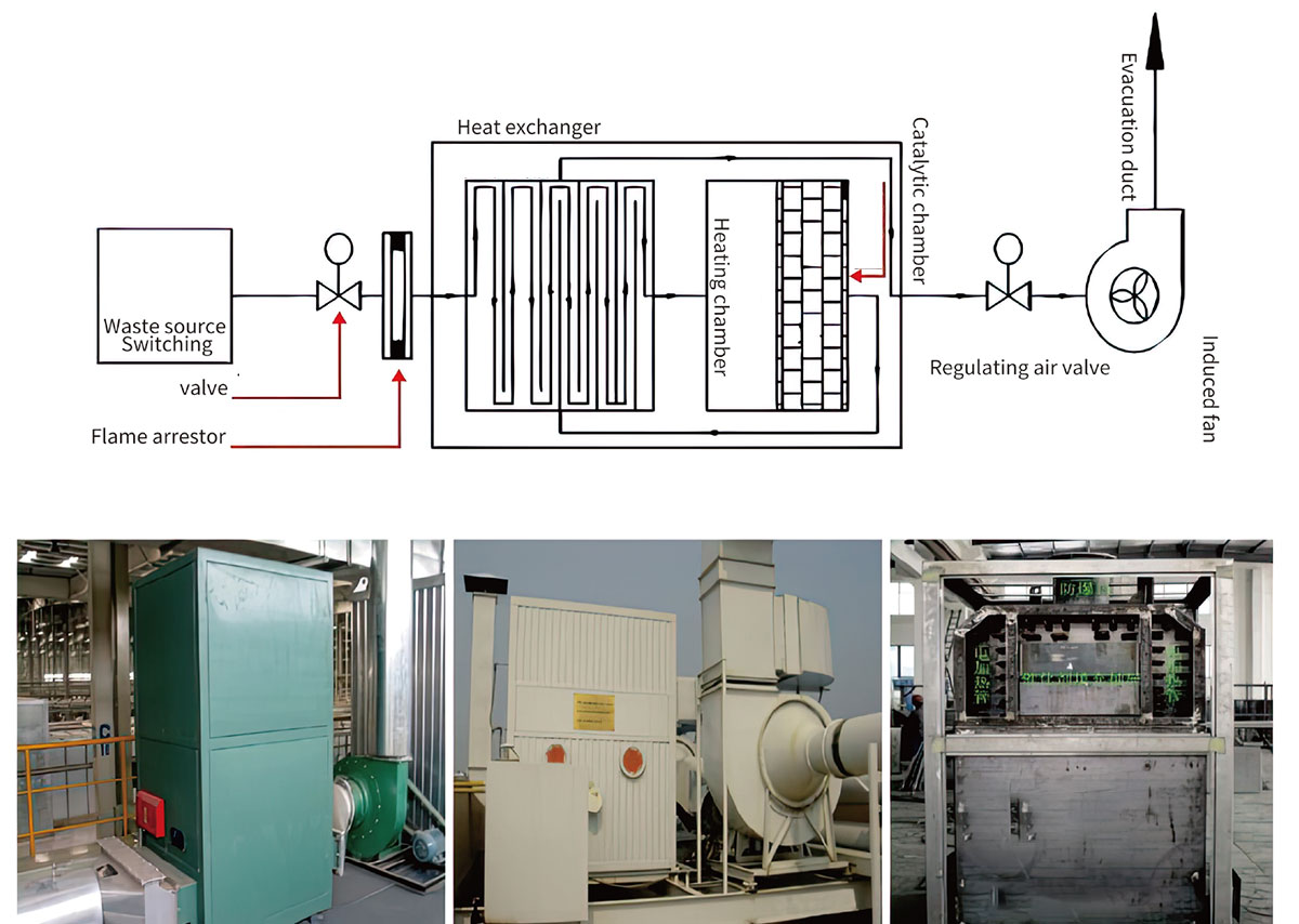
The organic gas source is sent into the purification device through the induced draft fan for heat exchange in the heat exchanger before entering the heating chamber. The gas is heated through the heating device to the catalytic reaction temperature, and then the organic gas is decomposed into carbon dioxide, water, and heat energy through the catalyst in the catalytic bed. The postreaction gas enters the heat exchanger again to exchange heat with the low-temperature gas and preheat the incoming gas. The heating system only needs to compensate for the heating through the control system to achieve complete combustion, saving energy, and the removal efficiency of the waste gas reaches over 97%, meeting national emission standards.

1.Low Energy Consumption:The catalytic ignition temperature is only 250-300°℃,and the equipment has a short preheating time of only 15-30 minutes. It consumes only the power of the blower when dealing with high concentrations, and automatically compen- sates for heating in low concentration intervals.
2.Low Resistance and High Purification rate:The honeycomb ceramic catalyst carrier impregnated with precious metals such as pal- adium and platinum is used, with a large surface area, long service life, and regenerative capabilities.
3.Waste Heat Recovery:The waste heat is used to preheat the gas to be treated,reducing the power consumption of the entire unit.
4.Safe and Reliable:The equipment is equipped with flame arrester and dust removal systems, explosion-proof venting systems, over-temperature alarm systems, and fully automatic control systems.
5.Small Footprint: Only 70%to 80%of similar products in the same industry.
6.High Purification Efficiency:The purification efficiency of the catalytic purification equipment can reach 97%or higher.
7.Easy Operation: The system is automatically controlled during operation.The CO series catalytic purification equipment uses ow-temperature oxidation technology, which is to heat organic gases to the decomposition temperature under the action of pre- cious metal catalysts to purify the gas.
| Specification Model | VOC-CO20 | VOC-CO50 | VOC-CO100 | VOC-C0200 | VOC-C0300 | VOC-CO500 | VOC-CO600 | VOC-C0800 | VOC-CO1000 | VOC-CO1800 | VOC-CO2000 | |
| reatment air volume (m3/h) | 200 | 500 | 1000 | 2000 | 3000 | 5000 | 6000 | 8000 | 10000 | 18000 | 20000 | |
| Organic gas concentration | 500~10000mg/m3( mixture gas) | |||||||||||
| Gas preheating temperature | 250~300℃ | |||||||||||
| Purification efficiency | ≥97% | |||||||||||
| Heating powerkw | 27 | 37.8 | 66 | 82.5 | 92.4 | 113.4 | 120 | 148.5 | 198 | 283.5 | 336 | |
| Mating fan | Model | BYX9-35 No4C | BYX9-35 No4.5C | BYX9-35 No5C | BYX9-35 No5C | BYX9-35 No5C | BYX9-35 No6.3C | BYX9-35 No6.3C | BYX9-35 No6.3C | BYX9-35 No8C | BOZGF100 OC | |
| Air volume (m2/h) | 600 | 1700 | 2706 | 4881 | 6610 | 9474 | 12595 | 15840 | 15627 | 27729 | 35000 | |
| Wind pressure (Pa) | 1700 | 1600 | 1800 | 2226 | 2226 | 2452 | 2500 | 2128 | 2540 | 2730 | 2300 | |
| Rotational speed rpm | 2000 | 2200 | 2000 | 2240 | 2240 | 1800 | 1450 | 1800 | 1450 | 1360 | ||
| Power (kw) | 1.5 | 3 | 4 | 5.5 | 7.5 | 11 | 15 | 15 | 18.5 | 37 | 55 | |
| Equipment size | Length (m) | 0.9 | 0.955 | 1.2 | 1.2 | 1.45 | 1.45 | 1.8 | 2.73 | 3.01 | 2.6 | 2.6 |
| width (m) | 0.6 | 0.66 | 0.9 | 1.28 | 1.28 | 1.54 | 1.76 | 1.43 | 1.48 | 2.4 | 2.4 | |
| height (m) | 1.45 | 1.83 | 2.08 | 2.15 | 2.31 | 2.31 | 2.54 | 2.2 | 2.73 | 3.14 | 3.14 | |
| Pipe | □(mm) | 120*120 | 160*160 | 200*200 | 250*250 | 320*320 | 400*400 | 460*450 | 550*550 | 630*630 | 800*800 | 850*850 |
| ⚪(mm) | φ120 | φ160 | φ200 | φ280 | φ360 | φ450 | φ500 | φ630 | φ700 | φ900 | φ1000 | |
| Weight(T) | 0.8 | 1.2 | 1.7 | 2.1 | 2.4 | 3.2 | 5.36 | 6.5 | 8 | 12 | 15 | |
Note:If the required air volume is not listed in the table,it can be designed separately.
Ensure the minimum air volume Q to prevent organic gas from spilling over
Q=K*F*V*3600m³/h
K is a safety factor of 1.05-1.10
F is the sum of the area of the ventilation ducts in m²
V is the minimum intake velocity to prevent gas from spiling over, which is 0.5-0.7 m/s.
2.Ensure a safe concentration when the solvent's evaporation concentration is less than 1/4 of the lower explosive limit (LEL)of the mixed gas.
M= the amount of organic solvent consumption per shift(g) / (the safe concentreion of the mixed gas(g/m³) * the actual woing time per shift(h))


